
Service Guide


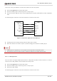


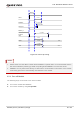
Table Of Contents
- Safety Information
- About the Document
- Contents
- Contents
- Table Index
- Figure Index
- 1 Introduction
- 2 Product Overview
- 3 Application Interfaces
- 3.1. General Description
- 3.2. Pin Assignment
- 3.3. Pin Description
- 3.4. Operating Modes
- 3.5. Power Saving
- 3.6. Power Supply
- 3.7. Turn on/Turn off/Reset
- 3.8. (U)SIM Interfaces
- 3.9. USB Interface
- 3.10. UART Interfaces
- 3.11. SPI Interface
- 3.12. I2C Interfaces
- 3.13. PCM Interface
- 3.14. Analog Audio Interfaces
- 3.15. LCD Interface
- 3.16. Matrix Keyboard Interface
- 3.17. SD Card Interface
- 3.18. WLAN Application Interface*
- 3.19. ADC Interfaces
- 3.20. Network Status Indication
- 3.21. STATUS
- 3.22. Behaviors of MAIN_RI
- 3.23. USB_BOOT Interface
- 4 Antenna Interfaces
- 5 Electrical Characteristics, Radio and Reliability
- 6 Mechanical Information
- 7 Storage, Manufacturing & Packaging
- 8 Appendix References

LTE Standard Module Series
EC200U_Series_Hardware_Design 34 / 94
PWRKEY
4.7K
47K
10 nF
Turn-on pulse
≥ 2 s
Figure 10: Turn on Module by Using Driving Circuit
Another way to control the PWRKEY is to use a button directly. When pressing the button, electrostatic
strike may generate from finger. Therefore, a TVS component is indispensable to be placed nearby the
button for ESD protection.
A reference circuit is shown in the following figure.
PWRKEY
S1
Close to S1
TVS
Figure 11: Turn on Module by Using Button
The power-up scenario is illustrated in the following figure.