
Service Guide


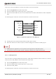


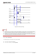
Table Of Contents
- Safety Information
- About the Document
- Contents
- Contents
- Table Index
- Figure Index
- 1 Introduction
- 2 Product Overview
- 3 Application Interfaces
- 3.1. General Description
- 3.2. Pin Assignment
- 3.3. Pin Description
- 3.4. Operating Modes
- 3.5. Power Saving
- 3.6. Power Supply
- 3.7. Turn on/Turn off/Reset
- 3.8. (U)SIM Interfaces
- 3.9. USB Interface
- 3.10. UART Interfaces
- 3.11. SPI Interface
- 3.12. I2C Interfaces
- 3.13. PCM Interface
- 3.14. Analog Audio Interfaces
- 3.15. LCD Interface
- 3.16. Matrix Keyboard Interface
- 3.17. SD Card Interface
- 3.18. WLAN Application Interface*
- 3.19. ADC Interfaces
- 3.20. Network Status Indication
- 3.21. STATUS
- 3.22. Behaviors of MAIN_RI
- 3.23. USB_BOOT Interface
- 4 Antenna Interfaces
- 5 Electrical Characteristics, Radio and Reliability
- 6 Mechanical Information
- 7 Storage, Manufacturing & Packaging
- 8 Appendix References

LTE Standard Module Series
EC200U_Series_Hardware_Design 29 / 94
In this case, three preconditions can make the module enter the sleep mode.
⚫ Execute AT+QSCLK=1 to enable sleep mode.
⚫ Ensure the MAIN_DTR is held at high level, or keep it open.
⚫ Ensure the host’s USB bus, which is connected with the module’s USB interface, enters suspended
state.
The following figure shows the connection between the module and the host.
USB_VBUS
USB_DP
USB_DM
AP_READY
VDD
USB_DP
USB_DM
GPIO
Module Host
GND
GND
MAIN_RI
EINT
Figure 5: Sleep Mode Application with MAIN_RI
⚫ Sending data to the module through USB can wake up the module.
⚫ When the module has a URC to report, the URC will trigger the behaviors of MAIN_RI pin.
1. USB suspend is supported on Linux system but not supported on Windows system.
2. Pay attention to the level match shown in dotted line between the module and the host.
3.5.1.4. USB Application
If the host does not support USB suspend function, USB_VBUS should be disconnected via an external
control circuit of USB_VBUS to let the module enter sleep mode.
⚫ Execute AT+QSCLK=1 to enable sleep mode.
⚫ Ensure the MAIN_DTR is held at high level, or keep it open.
⚫ Disconnect USB_VBUS.
The following figure shows the connection between the module and the host.
NOTE