
Service Guide


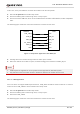


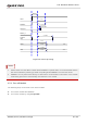
Table Of Contents
- Safety Information
- About the Document
- Contents
- Contents
- Table Index
- Figure Index
- 1 Introduction
- 2 Product Overview
- 3 Application Interfaces
- 3.1. General Description
- 3.2. Pin Assignment
- 3.3. Pin Description
- 3.4. Operating Modes
- 3.5. Power Saving
- 3.6. Power Supply
- 3.7. Turn on/Turn off/Reset
- 3.8. (U)SIM Interfaces
- 3.9. USB Interface
- 3.10. UART Interfaces
- 3.11. SPI Interface
- 3.12. I2C Interfaces
- 3.13. PCM Interface
- 3.14. Analog Audio Interfaces
- 3.15. LCD Interface
- 3.16. Matrix Keyboard Interface
- 3.17. SD Card Interface
- 3.18. WLAN Application Interface*
- 3.19. ADC Interfaces
- 3.20. Network Status Indication
- 3.21. STATUS
- 3.22. Behaviors of MAIN_RI
- 3.23. USB_BOOT Interface
- 4 Antenna Interfaces
- 5 Electrical Characteristics, Radio and Reliability
- 6 Mechanical Information
- 7 Storage, Manufacturing & Packaging
- 8 Appendix References

LTE Standard Module Series
EC200U_Series_Hardware_Design 27 / 94
Minimum
Functionality
Mode
AT+CFUN=0 can set the module to a minimum functionality mode without removing
the power supply. In this case, RF function will be invalid.
Airplane Mode
AT+CFUN=4 or W_DISABLE# can set the module to airplane mode. In this case, RF
function will be invalid.
Sleep Mode
In this mode, the current consumption of the module will be reduced to the minimal
level. In this mode, the module can still receive paging message, SMS, voice call and
TCP/UDP data from the network normally.
Power Down
Mode
In this mode, the power management unit (PMU) shuts down the power supply.
Software is not active, the serial interface is not accessible, while operating voltage
(connected to VBAT_RF and VBAT_BB) remains applied.
3.5. Power Saving
3.5.1. Sleep Mode
The module is able to reduce its current consumption to a minimum value in sleep mode. The following
section describes power saving procedures of the module.
3.5.1.1. UART Application
If the host communicates with module via UART interface, the following preconditions should be met to let
the module enter sleep mode.
⚫ Execute AT+QSCLK=1 to enable sleep mode.
⚫ Drive MAIN_DTR to high level.
The following figure shows the connection between the module and the host.
MAIN_RXD
MAIN_TXD
MAIN_RI
MAIN_DTR
AP_READY
TXD
RXD
EINT
GPIO
GPIO
Module
Host
GND
GND
Figure 3: Sleep Mode Application via UART