
Service Guide


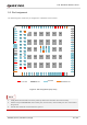
Table Of Contents
- Safety Information
- About the Document
- Contents
- Contents
- Table Index
- Figure Index
- 1 Introduction
- 2 Product Overview
- 3 Application Interfaces
- 3.1. General Description
- 3.2. Pin Assignment
- 3.3. Pin Description
- 3.4. Operating Modes
- 3.5. Power Saving
- 3.6. Power Supply
- 3.7. Turn on/Turn off/Reset
- 3.8. (U)SIM Interfaces
- 3.9. USB Interface
- 3.10. UART Interfaces
- 3.11. SPI Interface
- 3.12. I2C Interfaces
- 3.13. PCM Interface
- 3.14. Analog Audio Interfaces
- 3.15. LCD Interface
- 3.16. Matrix Keyboard Interface
- 3.17. SD Card Interface
- 3.18. WLAN Application Interface*
- 3.19. ADC Interfaces
- 3.20. Network Status Indication
- 3.21. STATUS
- 3.22. Behaviors of MAIN_RI
- 3.23. USB_BOOT Interface
- 4 Antenna Interfaces
- 5 Electrical Characteristics, Radio and Reliability
- 6 Mechanical Information
- 7 Storage, Manufacturing & Packaging
- 8 Appendix References

LTE Standard Module Series
EC200U_Series_Hardware_Design 13 / 94
Baseband
PMIC
Transceiver
PA
PAM
ANT_MAIN
VBAT_BB
VBAT_RF
PWRKEY
ADCs
VDD_EXT (U)SIMs UARTsI2Cs
Control
Duplex
Tx
PRx
SD
Card
STATUS
RESET_N
SAW
WLAN
ANT_BT/WIFI_SCAN
26 MHz
DCXO
SPI Nor Flash (64Mb)
PSRAM (128Mb)
LOUDSPK
MIC
ANT_GNSS
LCD
32 kHz Clock
GNSS
USB Keypads
SAW
LNA
APT
SPI
PCM
Figure 1: Functional Diagram
2.4. EVB
In order to help customers to develop applications with EC200U series, Quectel provides an evaluation
board (UMTS & LTE EVB), USB to RS-232 converter cable, earphone, antennas and other peripherals to
control or test the module. For more details, please refer to document [1].