
Product Info

Smart Module Series
SC20_Series_Hardware_Design 82 / 133
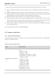
Table 44: GNSS Frequency
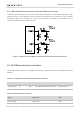
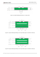
6.3.1. Recommended Circuit for Passive Antenna
GNSS antenna interface supports passive ceramic antennas and other types of passive antennas. A
reference circuit design is given below.
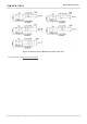
Figure 33: Reference Circuit Design for GNSS Passive Antenna
When the passive antenna is placed far away from the module (that is, the antenna trace is long), it is
recommended to add an external LNA circuit for better GNSS receiving performance, and the LNA should
be placed close to the antenna.
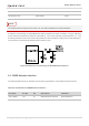
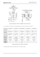
6.3.2. Recommended Circuit for Active Antenna
The active antenna is powered by a 56 nH inductor through the antenna's signal path. The common
power supply voltage ranges from 3.3 V to 5.0 V. Despite its low power consumption, the active antenna
still requires stable and clean power supplies. Therefore, it is recommended to use high-performance
LDO as the power supply. A reference design for GNSS active antenna is shown below.
Type Frequency Unit
GPS/Galileo 1575.42 ±1.023 MHz
GLONASS 1597.5–1605.8 MHz
BeiDou 1561.098 ±2.046 MHz
NOTE