
Product Info


Smart Module Series
SC20_Series_Hardware_Design 60 / 133
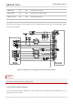
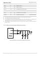
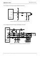
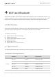
The following is a reference circuit design for rear camera interface, by taking the connection with T4KA3
camera as an example.
5
6
5
6
5
6
Figure 24: Reference Circuit Design for Rear Camera Interface
DVDD_1V2 is used to power the rear camera core, and VDD_AF_2V8 is used to power the rear camera
AF circuit. Both are powered by external LDOs.
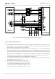
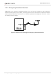
3.20.2. Front Camera Interface
The front camera interface integrates a one-lane MIPI_CSI for differential data transmission, and it
supports up to 2 MP camera.
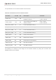
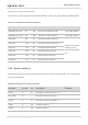
CAM0_RST 79 DO Reset of rear camera
CAM0_PWD 80 DO Power down of rear camera
CAM_I2C_SCL 83 OD I2C clock of camera
CAM_I2C_SDA 84 OD I2C data of camera
NOTE