
Product Info


Smart Module Series
SC20_Series_Hardware_Design 55 / 133
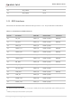
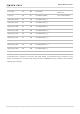
Table 21: Pin Definition of Motor Drive Interface
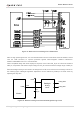
The motor is driven by an exclusive circuit, and the reference circuit design is shown below.
Figure 20: Reference Circuit for Motor Connection
When the motor stops, the redundant electricity can be discharged from the circuit loop formed by diodes,
thus avoiding damage to components.
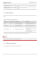
3.18. LCM Interface
SC20 series provides one LCM interface, which is MIPI_DSI standard compliant. The interface supports
high-speed differential data transmission with one 4-lane MIPI_DSI and a transmission rate of up to
1.5 Gbps/lane. It supports up to 720P resolution display.
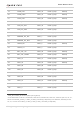
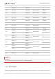
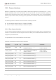
Table 22: Pin Definition of LCM Interface
Pin Name Pin No. I/O
Description Comment
VIB_DRV 28 PO Motor drive Connect it to the negative pole of the motor.
Pin Name Pin No. I/O Description Comment
LDO6_1V8 125 PO
1.8 V output power supply for
LCM I/O ports
Vnom = 1.8 V
I
O
max = 100 mA
LDO17_2V85 129 PO
2.85 V output power supply for
LCM VCC
Vnom = 2.85 V
I
O
max = 300 mA
PWM 29 DO PWM output
Adjust the backlight
brightness.