
Product Info


5G Module Series
RM500Q-AE&RM502Q-AE Hardware Design
RM500Q-AE&RM502Q-AE_Hardware_Design 57 / 83
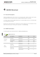
5.2. GNSS Antenna Interface
The following table shows frequency specification of GNSS antenna connector.
Table 272726: GNSS Frequency
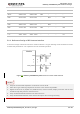
1. Keep the characteristic impedance for ANT3_GNSSL1 trace as 50 Ω.
2. Place the π-type matching components as close to the antenna as possible.
3. Digital circuits such as (U)SIM card, USB interface, camera module, display connector and SD card
should be kept away from the antenna traces.
4. Keep 75 dB isolation between two antenna traces.
5. Keep 15 dB isolation between each antenna to improve the receiving sensitivity.
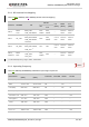
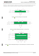
5.3. Reference Design of RF Layout
For user’s PCB, the characteristic impedance of all RF traces should be controlled as 50 Ω. The
impedance of the RF traces is usually determined by the trace width (W), the materials’ dielectric constant,
the height from the signal layer to reference ground (H), and the space between RF trace and ground (S).
Type
Frequency
Unit
GPS/Galileo/QZSS
1575.42 ±1.023 (L1)
MHz
Galileo
1575.42 ±2.046 (E1)
MHz
QZSS
1575.42 (L1)
MHz
GLONASS
1597.5–1605.8
MHz
BeiDou
1561.098 ±2.046
MHz
NOTES