
Product Info


LPWA Module Series
BG95 Hardware Design
BG95_Hardware_Design 67 / 88
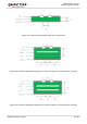
A reference design of GNSS antenna interface is shown as below.
Figure 30: Reference Circuit of GNSS Antenna Interface
1. An external LDO can be selected to supply power according to the active antenna requirement.
2. If the module is designed with a passive antenna, then the VDD circuit is not needed.
5.3. Antenna Installation
5.3.1. Antenna Requirements
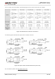
The following table shows the requirements on main antenna and GNSS antenna.
Table 35: Antenna Requirements
Antenna Type Requirements
GNSS
1)
Frequency range: 1559–1609 MHz
Polarization: RHCP or linear
VSWR: < 2 (Typ.)
Passive antenna gain: > 0 dBi
Active antenna noise figure: < 1.5 dB
Active antenna gain: > 0 dBi
Active antenna embedded LNA gain: < 17 dB
LTE/GSM
VSWR: ≤ 2
Efficiency: > 30%
NOTES