
Product Info


LPWA Module Series
BG95 Hardware Design
BG95_Hardware_Design 42 / 88
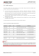
Table 9: Pin Definition of RESET_N
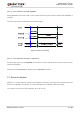
The reset scenario is illustrated in the following figure.
VBA T
≥ 2 s
Resetting
Module
Status
Running
RESET_N
V
IL
≤ 0.45 V
Restart
≤ 3.8 s
Figure 10: Reset Timing
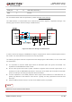
The recommended circuit is similar to the PWRKEY control circuit. An open drain/collector driver or button
can be used to control the RESET_N pin.
Reset pulse
RESET_N
4.7K
47K
2s~3.8s
Figure 11: Reference Circuit of RESET_N by Using Driving Circuit
Pin Name Pin No. Description DC Characteristics Comment
RESET_N 17 Reset the module V
IL
max = 0.45 V
Multiplexed from PWRKEY
(connected directly to PWRKEY
inside the module).