
Product Info


LPWA Module Series
BG95 Hardware Design
BG95_Hardware_Design 36 / 88
“*” means under development.
3.5. Power Supply
3.5.1. Power Supply Pins
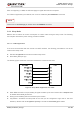
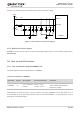
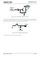
BG95 provides the following four VBAT pins for connection with an external power supply. There are two
separate voltage domains for VBAT.
Two VBAT_RF pins for module’s RF part.
Two VBAT_BB pins for module’s baseband part.
The following table shows the details of VBAT pins and ground pins.
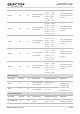
Table 7: VBAT and GND Pins
Pin Name Pin No. Description Module Min. Typ. Max. Unit
VBAT_RF 52, 53
Power supply for the
module’s RF part
BG95-M1/-M2/-N1
1)
2.6 3.3 4.8 V
BG95-M3/-M5 3.3 3.8 4.3 V
BG95-M4 3.8 V
VBAT_BB 32, 33
Power supply for the
module’s baseband
part
BG95-M1/-M2/-N1
1)
2.6 3.3 4.8 V
BG95-M3/-M5 3.3 3.8 4.3 V
BG95-M4 3.8 V
GND
3, 31, 48,
50, 54, 55,
58, 59, 61,
62, 67–74,
79–82,
89–91,
100–102
Ground - - - -
NOTE