
Product Info

Smart LTE Module Series
SC650T Hardware Design
SC650T_Hardware_Design 50 / 131
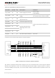
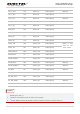
UART4_TXD
7
DO
UART4 transmit data
UART4_RXD
8
DI
UART4 receive data
UART5_RXD
198
DI
UART5 receive data
UART5_TXD
199
DO
UART5 transmit data
UART5_CTS
246
DI
UART5 clear to send
UART5_RTS
245
DO
UART5 request to send
UART6_RXD
61
DI
UART6 receive data
UART6_TXD
60
DO
UART6 transmit data
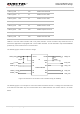
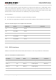
UART5 is a 4-wire UART interface with 1.8V power domain. A level translator chip should be used if
customers’ application is equipped with a 3.3V UART interface. A level translator chip TXS0104EPWR
provided by Texas Instruments is recommended.
The following figure shows a reference design.
VCCA
VCCB
OE
A1
A2
A3
A4
GND
B1
B2
B3
B4
LDO5_1P8
UART
5_ RTS
UART5_ RXD
UART
5_ CTS
UART5_ TXD
RXD_3.3V
CTS_3.3V
TXD_3.3V
VDD_3.3V
TXS0104EPWR
C1
100pF
C2
U1
100
pF
RTS_3.3V
Figure 13: Reference Circuit with Level Translator Chip (for UART5)
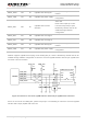
The following figure is an example of connection between SC650T and PC. A voltage level translator and
a RS-232 level translator chip are recommended to be added between the module and PC, as shown
below: