
Product Info


Smart Module Series
SC600Y&SC600T Hardware Design
SC600Y&SC600T_Hardware_Design 102 / 134
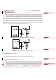
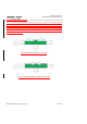
Figure 36: Reference Circuit Design for GNSS Active Antenna
6.4. Antenna Installation
6.4.1. Antenna Requirements
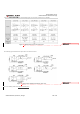
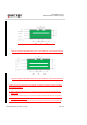
The following table shows the requirements on main antenna, Rx-diversity, Wi-Fi/BT antenna and GNSS antenna.
Table 39
: Antenna Requirements
1)
It is recommended to use a passive GNSS antenna when LTE B13 or B14 is supported, as the use of
active antenna may generate harmonics which will affect the GNSS performance.
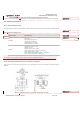
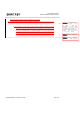
6.4.2. Recommended RF Connector for Antenna Installation
If RF connector is used for antenna connection, it is recommended to use the U.FL-R-SMT connector provided by
HIROSE.
Figure 37
: Dimensions of the U.FL-R-SMT Connector (Unit: mm)
Antenna Type Requirements
Wi-Fi/BT
VSWR: ≤2
Gain (dBi): 1
Max Input Power (W): 50
Input Impedance (Ω): 50
Polarization Type: Vertical
Cable Insertion Loss: <1dB
GNSS
1)
Frequency range: 1559MHz~1609MHz
Polarization: RHCP or linear
VSWR: <2 (Typ.)
Passive Antenna Gain: >0dBi
Active Antenna Noise Figure: <1.5dB (Typ.)
Active Antenna Gain: >-2dBi
Active Antenna Embedded LNA Gain: <17dB (Typ.)
Active Antenna Total Gain: <17dBi (Typ.)
NOTE
删除的内容: 41
删除的内容: 42
带格式表格
删除的内容: GSM/WCDMA/
LTE
... [10]
删除的内容: 42