
Product Info


Smart Module Series
SC600Y&SC600T Hardware Design
SC600Y&SC600T_Hardware_Design 100 / 134
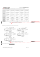
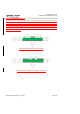
Table 36: Wi-Fi/BT/FM Frequency
A
refere
nce
circuit
desig
n for
Wi-Fi/
BT/F
M
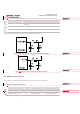
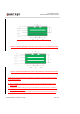
antenna interface is shown as below. A π-type matching circuit is recommended to be reserved for better RF
performance. The capacitors are not mounted by default and resistors are 0Ω.
Figure 33
: Reference Circuit Design for Wi-Fi/BT Antenna Interface
Figure 34: Reference Circuit Design for FM Antenna Interface
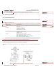
6.3. GNSS Antenna Interface
The pin definition of GNSS antenna interfaces and operating frequencies is shown below.
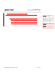
Table 37
: Pin Definition of GNSS Antenna
Table
38
:
GNS
S
Frequ
Type Frequency Unit
802.11a/b/g/n/ac
2402~2482
5180~5825
MHz
BT4.2 LE 2402~2480 MHz
FM 76~108 MHz
Pin Name Pin No. I/O Description Comment
ANT_GNSS 134 AI GNSS antenna Interface 50Ω impedance
GNSS_LNA_EN 202 DO LNA enable control
For test purpose only.
If unused, keep it open.
删除的内容: 39
删除的内容: 38
删除的内容: 39
删除的内容: 40
删除的内容: 41