
Product Info

Smart Module Series
SC600Y&SC600T Hardware Design
SC600Y&SC600T_Hardware_Design 79 / 134
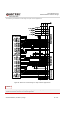
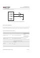
3.23. Audio Interfaces
SC600Y/SC600T provides three analog input channels and three analog output channels. The following
table shows the pin definition.
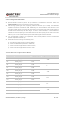
Table 28: Pin Definition of Audio Interfaces
Pin Name Pin No. I/O Description Comment
MIC1_P 44 AI Microphone input for channel 1 (+)
MIC1_N 45 AI Microphone input for channel 1 (-)
MIC_GND 168 Microphone reference ground
If unused, connect this
pin to the ground.
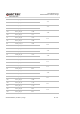
MIC2_P 46 AI Microphone input for headset (+)
MIC3_P 169 AI Microphone input for channel 2 (+)
MIC_BIAS 167 AO Microphone bias voltage
EAR_P 53 AO Earpiece output (+)
EAR_N 52 AO Earpiece output (-)
SPK_P 55 AO Speaker output (+)
SPK_N 54 AO Speaker output (-)
HPH_R 51 AO Headphone right channel output
HPH_REF 50 AI Headphone reference ground
It should be connected
to main GND.
HPH_L 49 AO Headphone left channel output
HS_DET 48 AI Headset insertion detection High level by default.
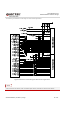
The module offers three audio input channels, including one differential input pair and two
single-ended channels. The three sets of MICs are integrated with internal bias voltage.
The output voltage range of MIC_BIAS is programmable between 1.6V and 2.85V, and the maximum
output current is 3mA.
The earpiece interface uses differential output.
The loudspeaker interface uses differential output as well. The output channel is available with a
Class-D amplifier whose maximum output power is 1.5W when load is 8Ω.
The headphone interface features stereo left and right channel output, and headphone insertion
detection function is supported.