
Product Info

Smart Module Series
SC600Y&SC600T Hardware Design
SC600Y&SC600T_Hardware_Design 70 / 134
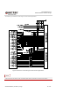
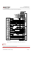
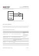
3.21. Camera Interfaces
Based on standard MIPI CSI input interface, SC600Y/SC600T supports 3 cameras (4-lane + 4-lane +
4-lane) or 4 cameras (4-lane + 4-lane + 2-lane + 1-lane), with maximum pixels up to 21MP for SC600Y
and 24MP for SC600T. The video and photo quality are determined by various factors such as camera
sensor, camera lens quality, etc.
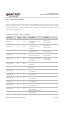
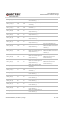
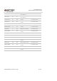
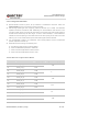
Table 24: Pin Definition of Camera Interfaces
Pin Name Pin No. I/O Description Comment
LDO2_1P1 13 PO
1.1V output power supply
for digital core circuit of
rear camera
Vnorm=1.1V
I
O
max=1200mA
LDO6_1P8 10 PO
1.8V output power supply
for digital I/O circuit of
camera
Vnorm=1.8V
I
O
max=300mA
LDO17_2P85 12 PO
2.85V output power supply
auto focus circuit
Vnorm=2.85V
I
O
max=300mA
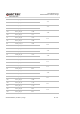
LDO22_2P8 14 PO
2.8V output power supply
for AVDD of cameras
Vnorm=2.8V
I
O
max=150mA
LDO23_1P2 15 PO
1.2V output power supply
for digital core circuit of
front camera
Vnorm=1.2V
I
O
max=600mA
CSI0_CLK_N 89 AO
MIPI clock signal of rear
camera (-)
CSI0_CLK_P 88 AO
MIPI clock signal of rear
camera (+)
CSI0_LN0_N 91 AI
MIPI lane 0 data signal of
rear camera (-)
CSI0_LN0_P 90 AI
MIPI lane 0 data signal of
rear camera (+)
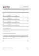
CSI0_LN1_N 93 AI
MIPI lane 1 data signal of
rear camera (-)
CSI0_LN1_P 92 AI
MIPI lane 1 data signal of
rear camera (+)
CSI0_LN2_N 95 AI
MIPI lane 2 data signal of
rear camera (-)
CSI0_LN2_P 94 AI
MIPI lane 2 data signal of
rear camera (+)
CSI0_LN3_N 97 AI
MIPI lane 3 data signal of
rear camera (-)