
Product Info

Smart Module Series
SC600Y&SC600T Hardware Design
SC600Y&SC600T_Hardware_Design 68 / 134
Power two strings of WLEDs (about 14 WLEDs) with two current sink drivers, or power four strings of
WLEDs (about 24 WLEDs) with four current sink drivers.
The duty ratio of PWM can be configured by software to adjust the backlight brightness.
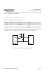
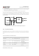
LCM0 uses the internal backlight driving circuit provided by SC600Y/SC600T by default. LCM1 can use
the internal circuit or an external backlight driving circuit according to customers’ demands. The following
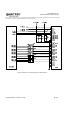
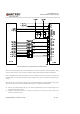
is a reference design for LCM1 external backlight driving circuit where PMU_MPP4 is used to adjust the
backlight brightness.
Figure 22: Reference Design of LCM1 External Backlight Driving Circuit
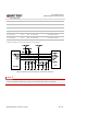
3.20. Touch Panel Interfaces
SC600Y/SC600T provides two I2C interfaces for connection with touch panel, and also provides the
corresponding power supply and interrupt pins. The pin definition of touch panel interfaces is illustrated
below.
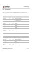
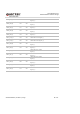
Table 23: Pin Definition of Touch Panel Interfaces
Pin Name Pin No I/O Description Comment
LDO10_2P8 11 PO 2.8V output power supply.
Vnorm=2.8V
I
O
max=150mA
LDO6_1P8 10 PO 1.8V output power supply.
Pull-up power supply of I2C
Vnorm=1.8V
I
O
max=300mA
TP0_INT 139 DI TP0 Interrupt 1.8V power domain.
TP0_RST 138 DO TP0 reset
1.8V power domain.
Active low.