
Product Info

Smart Module Series
SC600Y&SC600T Hardware Design
SC600Y&SC600T_Hardware_Design 67 / 134
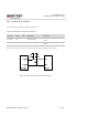
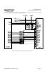
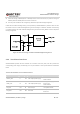
Figure 21: Reference Circuit Design for LCM1 Interface
MIPI are high speed signal lines. It is recommended that common-mode filters should be added in series
near the LCM connector, so as to improve protection against electromagnetic radiation interference.
When compatible design with other displays is required, please connect the LCD_ID pin of LCM to the
module’s ADC pin, and please note that the output voltage of LCD_ID cannot exceed the voltage range of
ADC pin.
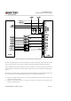
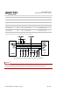
Backlight driving circuits should be designed for LCMs. SC600Y/SC600T provide backlight driving output
which can be used to drive LCM backlight WLEDs directly. The features are listed below:
Use the high voltage output (LCD_BL_A) for powering WLED strings, and the output voltage can be
configured from VBAT to 29.5V.
Support 4 current sinks (LCD_BL_K1, LCD_BL_K2, LCD_BL_K3, LCD_BL_K4), with maximum sink
current up to 25mA for each.