
Product Info

Smart Module Series
SC600Y&SC600T Hardware Design
SC600Y&SC600T_Hardware_Design 51 / 134
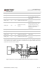
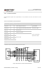
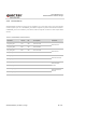
The following figure is an example of connection between SC600Y/SC600T and PC. A voltage level
translator and a RS-232 level translator chip are recommended to be added between the module and PC,
as shown below:
Figure 15: RS232 Level Match Circuit (for UART5)
UART2, UART4 and UART6 are similar to UART5. Please refer to UART5 reference circuit design for that
of the UART2, UART4 and UART6.
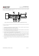
3.11. (U)SIM Interfaces
SC600Y/SC600T provides two (U)SIM interfaces which both meet ETSI and IMT-2000 requirements.
Dual SIM Dual Standby is supported by default. Both 1.8V and 2.95V (U)SIM cards are supported, and
the (U)SIM interfaces are powered by the dedicated low dropout regulators in SC600Y/SC600T module.
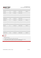
Table 13: Pin Definition of (U)SIM Interfaces
Pin Name Pin No. I/O Description Comment
USIM1_DET 145 DI
(U)SIM1 card hot-plug
detection
Active Low.
Require external pull-up to 1.8V.
If unused, keep this pin open.
Disabled by default, and can be
enabled through software
configuration.
NOTE