
Product Info

Smart Module Series
SC600Y&SC600T Hardware Design
SC600Y&SC600T_Hardware_Design 49 / 134
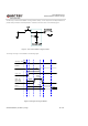
172 USB_SS_RX_M 28.23
174 USB_SS_TX_P 19.58
0.23
175 USB_SS_TX_M 19.35
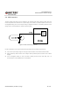
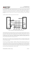
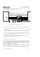
3.10. UART Interfaces
The module provides the following four UART interfaces:
UART5: 4-wire UART interface, hardware flow control supported.
UART6: 4-wire UART interface, hardware flow control supported, multiplexed from SPI interface.
UART2: 2-wire UART interface, used for debugging.
UART4: 2-wire UART interface.
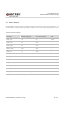
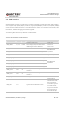
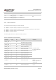
The following table shows the pin definition of UART interfaces.
Table 12: Pin Definition of UART Interfaces
Pin Name Pin No. I/O Description Comment
UART2_TXD 5 DO
UART2 transmit data.
Used for debugging by default
1.8V power domain.
If unused, keep these
pins open.
UART2_RXD 6 DI
UART2 receive data.
Used for debugging by default
UART4_TXD 7 DO UART4 transmit data
UART4_RXD 8 DI UART4 receive data
UART5_RXD 198 DI UART5 receive data
UART5_TXD 199 DO UART5 transmit data
UART5_CTS 246 DI UART5 clear to send
UART5_RTS 245 DO UART5 request to send
SPI_MISO 61 DI UART6 receive data
SPI interface pin by
default.
Can be multiplexed into
UART6_RXD.
SPI_MOSI 60 DO UART6 transmit data
SPI interface pin by
default.