
Product Info

Smart Module Series
SC600Y&SC600T Hardware Design
SC600Y&SC600T_Hardware_Design 38 / 134
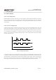
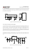
In addition, in order to get a stable power source, it is suggested to use a 0.5W TVS and place it as close
to the VBAT pins as possible to increase voltage surge withstand capability. The following figure shows
the structure of the power supply.
Figure 4: Star Structure of Power Supply
3.4.3. Reference Design for Power Supply
The power design for the module is very important, as the performance of module largely depends on the
power source. The power supply of SC600Y/SC600T should be able to provide sufficient current up to 3A
at least. By default, it is recommended to use a battery to supply power for SC600Y/SC600T. But if
battery is not intended to be used, it is recommended to use a regulator for SC600Y/SC600T. If the
voltage difference between the input and output is not too high, it is suggested to use an LDO to supply
power for the module. If there is a big voltage difference between the input source and the desired output
(VBAT), a buck converter is preferred to be used as the power supply.
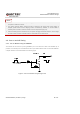
The following figure shows a reference design for +5V input power source which adopts an LDO
(MIC29502WU) from MICROCHIP. The typical output voltage is 3.8V and the maximum rated current is
5.0A.
Figure 5: Reference Circuit of Power Supply