
Product Info

Smart Module Series
SC600Y&SC600T Hardware Design
SC600Y&SC600T_Hardware_Design 37 / 134
3.4. Power Supply
3.4.1. Power Supply Pins
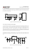
SC600Y/SC600T provides 3 VBAT pins and 2 VPH_PWR pins. VBAT pins are dedicated for connection
with an external power supply. VPH_PWR pins can supply power for peripherals, and it can provide a
maximum continuous current of 1A approximately. The value of capacitors placed on this pin should not
exceed 120uF.
3.4.2. Decrease Voltage Drop
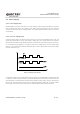
The power supply range of the module is from 3.55V to 4.4V, and the recommended value is 3.8V. The
power supply performance, such as load capacity, voltage ripple, etc. directly influences the module’s
performance and stability. Under ultimate conditions, the module may have a transient peak current up to
3A. If the power supply capability is not sufficient, there will be voltage drops, and if the voltage drops
below 3.1V, the module will be powered off automatically. Therefore, please make sure the input voltage
will never drop below 3.1V.
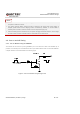
Figure 3: Voltage Drop Sample
To decrease voltage drop, a bypass capacitor of about 100µF with low ESR (ESR=0.7Ω) should be used
in VBAT pins, and a multi-layer ceramic chip capacitor (MLCC) array should also be reserved due to its
ultra-low ESR. It is recommended to use three ceramic capacitors (100nF, 33pF, 10pF) for composing the
MLCC array, and place these capacitors close to VBAT/VDD_RF/VPH_PWR pins. The width of VBAT
trace should be no less than 3mm. In principle, the longer the VBAT trace is, the wider it will be.