
Product Info


LPWA Module Series
BG95-M3 Mini PCIe Hardware Design
BG95-M3_Mini_PCIe_Hardware_Design 26 / 53
PCM and I2C interfaces support VoLTE and GSM CS voice only.
3.7. Control and Indication Interfaces
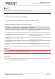
The following table shows the pin definition of control and indication interfaces.
Table 10: Pin Definition of Control and Indication Interfaces
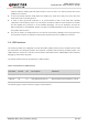
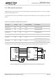
The module can be reset by driving PERST# low for 2–3.8 s.
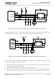
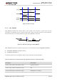
3.7.1. RI
RI is used to wake up the host. When a URC returns, there will be the following behaviors on the RI pin
after executing AT+QCFG="risignaltype","physical".
Pin Name Pin No. I/O Power Domain Description
RI 17 DO 3.3 V Used to wake up the host.
DTR 31 DI 3.3 V Data terminal ready.
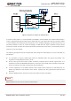
W_DISABLE# 20 DI 3.3 V
Airplane mode control.
Pulled up by default. Active low.
PERST# 22 DI 3.3 V
Fundamental reset signal.
Pulled up by default. Active low.
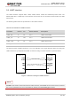
LED_WWAN# 42 OC
LED signal for indicating the network status of
the module. Active low.
WAKE# 1 OC
Used to wake up the host.
NOTE
NOTE