
Product Info


LPWA Module Series
BG95-M3 Mini PCIe Hardware Design
BG95-M3_Mini_PCIe_Hardware_Design 25 / 53
3.6. PCM and I2C Interfaces*
BG95-M3 Mini PCIe provides one Pulse Code Modulation (PCM) digital interface and one I2C interface
for VoLTE and GSM CS voice.
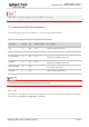
The following table shows the pin definition of PCM and I2C interfaces that can be applied in audio codec
design.
Table 9: Pin Definition of PCM and I2C Interfaces
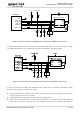
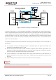
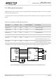
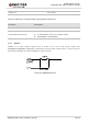
The following figure shows a reference design of PCM and I2C interfaces with an external codec IC.
Figure 8: Reference Design of PCM and I2C Application with Audio Codec
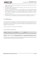
Pin Name Pin No. I/O Power Domain Description
PCM_CLK 45 DO 1.8 V PCM clock signal
PCM_DOUT 47 DO 1.8 V PCM data output
PCM_DIN 49 DI 1.8 V PCM data input
PCM_SYNC 51 DO 1.8 V PCM frame synchronization
I2C_SCL 30 OD 1.8 V
I2C serial clock.
Require external pull-up to 1.8 V.
I2C_SDA 32 OD 1.8 V
I2C serial data.
Require external pull-up to 1.8 V.