
Product Info


LPWA Module Series
BG95-M3 Mini PCIe Hardware Design
BG95-M3_Mini_PCIe_Hardware_Design 20 / 53
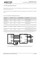
LDO_IN
C1
C2
MIC29302WU U1
IN OUT
24
VCC_3V3
100nF
C3
470uF
C4
100nF
R2
82K 1%
47K 1%
R3
470uF
470R
51K
R4
R1
MCU_POWER
_ON/OFF
47K
4.7K
R5
R6
C5
C6
33pF
10pF
TVS
D1
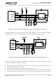
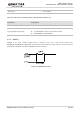
Figure 3: Reference Design of Power Supply
3.3. (U)SIM Interface
The (U)SIM interface circuitry meets ETSI and IMT-2000 requirements. Only 1.8 V (U)SIM card is
supported. The following table shows the pin definition of (U)SIM interface.
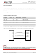
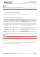
Table 7: Pin Definition of (U)SIM Interface
BG95-M3 Mini PCIe supports (U)SIM card hot-plug via USIM_DET, and both high and low level detection
are supported. The function is disabled by default. See AT+QSIMDET in document [2] for details.
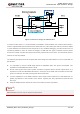
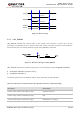
The following figure shows a reference design of (U)SIM interface with an 8-pin (U)SIM card connector.
Pin Name Pin No. I/O Power Domain Description
USIM_VDD 8 PO 1.8 V (U)SIM card power supply
USIM_DATA 10 IO 1.8 V (U)SIM card data
USIM_CLK 12 DO 1.8 V (U)SIM card clock
USIM_RST 14 DO 1.8 V (U)SIM card reset
USIM_DET 44 DI 1.8 V (U)SIM card insertion detection