
Product Info


LPWA Module Series
BG95-M3 Mini PCIe Hardware Design
BG95-M3_Mini_PCIe_Hardware_Design 13 / 53
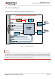
2.3. Functional Diagram
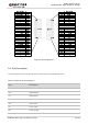
The following figure shows the block diagram of BG95-M3 Mini PCIe.
Figure 1: Functional Diagram
The integrated (U)SIM card connector shares the same (U)SIM bus with the external (U)SIM card
connector that is connected to Mini PCI Express (U)SIM interface. It does not support (U)SIM card
detection function, and cannot be used simultaneously with the external (U)SIM card connector. When
unused, it has no any effect to the external (U)SIM card connector.
NOTE