
Product Info


LTE Standard Module Series
EG95 Hardware Design
EG95_Hardware_Design 41 / 93
Module
USIM_VDD
USIM_GND
USIM_RST
USIM_CLK
USIM_DATA
USIM_PRESENCE
0R
0R
0R
VDD_EXT
51K
100nF (U)SIM Card Connector
GND
GND
33pF
33pF 33pF
VCC
RST
CLK
IO
VPP
GND
GND
USIM_VDD
15K
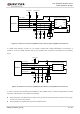
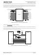
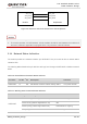
Figure 17: Reference Circuit of (U)SIM Interface with an 8-pin (U)SIM Card Connector
If (U)SIM card detection function is not needed, please keep USIM_PRESENCE unconnected. A
reference circuit of (U)SIM interface with a 6-pin (U)SIM card connector is illustrated in the following
figure.
Module
USIM_VDD
USIM_GND
USIM_RST
USIM_CLK
USIM_DATA
0R
0R
0R
100nF
(U)SIM Card Connector
GND
33pF 33pF 33pF
VCC
RST
CLK IO
VPP
GND
GND
15K
USIM_VDD
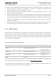
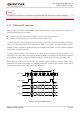
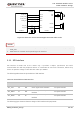
Figure 18: Reference Circuit of (U)SIM Interface with a 6-pin (U)SIM Card Connector
In order to enhance the reliability and availability of the (U)SIM cards in customers’ applications, please
follow the criteria below in the (U)SIM circuit design:
⚫ Keep placement of (U)SIM card connector to the module as close as possible. Keep the trace length
as less than 200mm as possible.
⚫ Keep (U)SIM card signals away from RF and VBAT traces.