
Product Info


LTE-A Module Series
EG12 Hardware Design
EG12_Hardware_Design 65 / 100
Module
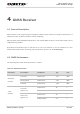
USB_BOOT
VDD_EXT
10K
Test point
TVS
Close to module
Figure 32: Reference Circuit of USB_BOOT Interface
3.22. GPIOs
The module provides 5 GPIOs for customers’ design.
Table 29: Pin Definition of GPIOs
Pin Name
Pin No.
I/O
Description
Comment
GPIO_1
138
IO
General purpose input/output port
If unused, keep it open.
GPIO_2
139
IO
If unused, keep it open.
GPIO_3
159
IO
If unused, keep it open.
GPIO_4
161
IO
If unused, keep it open.
GPIO_5
172
IO
If unused, keep it open.