
Product Info


LTE-A Module Series
EG12 Hardware Design
EG12_Hardware_Design 57 / 100
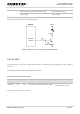
A reference circuit is shown in the following figure.
4.7K
47K
VBAT
2.2K
Module
Network
Indicator
Figure 27: Reference Circuit of the Network Indicator
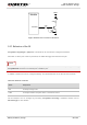
3.16. STATUS
The STATUS pin is set as the module status indicator. It outputs high level voltage when the module is
turned on.
The following table describes pin definition of STATUS.
Table 23: Pin Definition of STATUS
A reference circuit is shown as below.
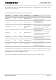
Flicker quickly (125ms High/125ms Low)
Data transfer ongoing
Always High
Voice calling
Pin Name
Pin No.
I/O
Description
Comment
STATUS
171
DO
Indicate the module’s operation status
1.8V power domain
If unused, keep it open.