
Product Info


LTE-A Module Series
EG12 Hardware Design
EG12_Hardware_Design 52 / 100
SPI_CS_N
SPI_CLK
SPI_MOSI
MSB
1 2
SPI_MISO
3
T
t(mov)
4
t(mis)
t(mih)
t(ch) t(cl)
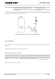
Figure 23: Timing of SPI Interface
The related parameters of SPI timing are shown in the following table.
Table 17: Parameters of SPI Interface Timing
3.13. PCM and I2C Interfaces
EG12 supports audio communication via Pulse Code Modulation (PCM) digital interface and I2C
interfaces. The PCM interface supports the following modes:
Primary mode (short frame synchronization, works as both master and slave)
Auxiliary mode (long frame synchronization, works as master only)
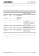
Parameter
Description
Min.
Typ.
Max.
Unit
T
SPI clock period
20.0
-
-
ns
t(ch)
SPI clock high level time
9.0
-
-
ns
t(cl)
SPI clock low level time
9.0
-
-
ns
t(mov)
SPI master data output valid time
-5.0
-
5.0
ns
t(mis)
SPI master data input setup time
5.0
-
-
ns
t(mih)
SPI master data input hold time
1.0
-
-
ns