
Product Info


LTE-A Module Series
EG12 Hardware Design
EG12_Hardware_Design 49 / 100
3.11.2. Debug UART Interface
The following table shows the Debug UART interface pin definition.
Table 13: Pin Definition of Debug UART Interface
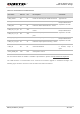
3.11.3. BT UART Interface
The following table shows the BT UART interface pin definition.
Table 14: Pin Definition of the BT UART Interface
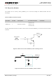
3.11.4. UART Application
EG12 provides 1.8V UART interfaces. A level translator should be used if the application is equipped with
a 3.3V UART interface. A level translator TXS0108EPWR provided by Texas Instruments is
recommended. The following figure shows a reference design.
The logic levels are described in the following table.
RI
61
DO
Ring indication
1.8V power domain
DTR
62
DI
Data terminal ready,
sleep mode control
1.8V power domain
Pin Name
Pin No.
I/O
Description
Comment
DBG_RXD
136
DI
Receive data
1.8V power domain
DBG_TXD
137
DO
Transmit data
1.8V power domain
Pin Name
Pin No.
I/O
Description
Comment
BT_EN
3
DO
BT function enable
control
1.8V power domain
If unused, keep it open.
BT_TXD
163
DO
Transmit data
BT_CTS
164
DO
Clear to send
BT_RXD
165
DI
Receive data
BT_RTS
166
DI
Request to send