
Product Info


LTE-A Module Series
EG12 Hardware Design
EG12_Hardware_Design 46 / 100
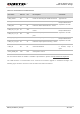
Table 11: Pin Definition of USB Interface
For more details about the USB 2.0 & USB 3.0 specifications, please visit http://www.usb.org/home.
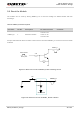
The USB interface is recommended to be reserved for firmware upgrade in customers’ designs. The
following figure shows a reference circuit of USB 2.0 & USB 3.0 interface.
Pin Name
Pin No.
I/O
Description
Comment
USB_VBUS
32
PI
Used for detecting the USB connection
Typical 5.0V
USB_DP
34
IO
USB 2.0 differential data bus - plus
Require differential
impedance of 90Ω
USB_DM
33
IO
USB 2.0 differential data bus - minus
USB_SS_ TX_M
37
AO
USB 3.0 super-speed transmission -
minus
Require differential
impedance of 90Ω
USB_SS_ TX_P
38
AO
USB 3.0 super-speed transmission -
plus
USB_SS_ RX_P
40
AI
USB 3.0 super-speed receiving - plus
Require differential
impedance of 90Ω
USB_SS_ RX_M
41
AI
USB 3.0 super-speed receiving - minus
USB_ID
36
DI
OTG identification
1.8V power domain.
If unused, keep it
open
OTG_PWR_EN
143
DO
OTG power control