
Product Info


LTE-A Module Series
EG12 Hardware Design
EG12_Hardware_Design 44 / 100
EG12 supports (U)SIM card hot-plug via USIM_DET pins. The function supports low level and high level
detections, and is disabled by default. Please refer to document [2] for more details about AT+QSIMDET
command.
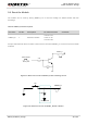
The following figure shows a reference design for a (U)SIM interface with an 8-pin (U)SIM card connector.
Module
USIM_VDD
USIM_RST
USIM_CLK
USIM_DATA
USIM_DET
22R
22R
22R
VDD_EXT
51K
100nF (U)SIM Card Connector
GND
GND
VCC
RST
CLK
IO
VPP
GND
USIM_VDD
15K
NM NM NM
CD1 CD2
Figure 18: Reference Circuit of a (U)SIM Interface with an 8-Pin (U)SIM Card Connector
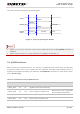
If (U)SIM card detection function is not needed, please keep USIM_DET pins unconnected. A reference
circuit for a (U)SIM interface with a 6-pin (U)SIM card connector is illustrated in the following figure.
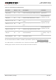
USIM1_DATA
29
IO
Data signal of (U)SIM1 card
USIM2_VDD
74
PO
Power supply for (U)SIM2 card
Either 1.8V or 3.0V is supported
by the module automatically.
If (U)SIM2 interface is unused,
keep it open.
USIM2_
DATA
77
IO
Data signal of (U)SIM2 card
If (U)SIM2 interface is unused,
keep it open.
USIM2_DET
78
DI
(U)SIM2 card insertion detection
If (U)SIM2 interface is unused,
keep it open.
USIM2_RST
79
DO
Reset signal of (U)SIM2 card
If (U)SIM2 interface is unused,
keep it open.
USIM2_CLK
80
DO
Clock signal of (U)SIM2 card
If (U)SIM2 interface is unused,
keep it open.