
Product Info


LTE-A Module Series
EG12 Hardware Design
EG12_Hardware_Design 43 / 100
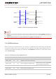
The reset scenario is illustrated in the following figure.
V
IL
≤0.5V
V
IH
≥1.3V
VBAT
≥250ms
Resetting
Module
Status
Running
RESET_N
Restart
≤600ms
Figure 17: Timing of Resetting the Module
1. RESET_N can only be used when turning off the module failed either by AT+QPOWD command or
PWRKEY.
2. Please ensure that there is no large capacitance on PWRKEY and RESET_N.
3.9. (U)SIM Interfaces
EG12 provides two (U)SIM interfaces. The circuitry of (U)SIM interfaces meets ETSI and IMT-2000
requirements. Either 1.8V or 3.0V (U)SIM cards are supported. Dual SIM Single Standby function is
supported and (U)SIM card switching is enabled by AT+QUIMSLOT command. For more details, please
refer to document [2].
Table 10: Pin Definition of the (U)SIM Interfaces
Pin Name
Pin No.
I/O
Description
Comment
USIM1_DET
25
DI
(U)SIM1 card insertion detection
USIM1_VDD
26
PO
Power supply for (U)SIM1 card
Either 1.8V or 3.0V is supported
by the module automatically.
USIM1_CLK
27
DO
Clock signal of (U)SIM1 card
USIM1_RST
28
DO
Reset signal of (U)SIM1 card
NOTES