
Product Info


LTE-A Module Series
EG12 Hardware Design
EG12_Hardware_Design 36 / 100
Table 6: RF Function Status
1. The W_DISABLE# control function is disabled in firmware by default. It can be enabled by
AT+QCFG="airplanecontrol" command, and this command is under development.
2. The execution of AT+CFUN command will not affect GNSS function.
3.6. Power Supply
3.6.1. Power Supply Pins
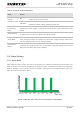
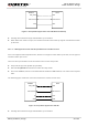
EG12 provides six VBAT pins dedicated to connection with an external power supply. There are two
separate voltage domains for VBAT.
Four VBAT_RF pins for module’s RF part
Two VBAT_BB pins for module’s baseband part
The following table shows details of VBAT pins and ground pins.
Table 7: VBAT and GND Pins
W_DISABLE#
AT Commands
RF Function
Module Operation
High Level
AT+CFUN=1
RF Enabled
Normal mode
AT+CFUN=0
AT+CFUN=4
RF Disabled
AT+CFUN=0: Minimum functionality mode
AT+CFUN=4: Airplane mode
Low Level
AT+CFUN=0
AT+CFUN=1
AT+CFUN=4
RF Disabled
Airplane mode
Pin Name
Pin No.
Description
Min.
Typ.
Max.
Unit
VBAT_RF
85, 86
87, 88
Power supply for the
module’s RF part
3.3
3.8
4.3
V
VBAT_BB
155, 156
Power supply for the
module’s baseband part
3.3
3.8
4.3
V
GND
10, 13, 16, 17, 24, 30,
31, 35, 39, 44, 45, 54,
55, 63, 64, 69, 70, 75,
76, 81~84, 89, 90,
Ground
-
0
-
V
NOTES