
Product Info

LTE Standard Module Series
EC21 Mini PCIe Hardware Design
EC21_Mini_PCIe_Hardware_Design 29 / 64
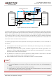
2. The ESD device used for USB interface protection has been built in the Mini PCIe, thus the external
ESD device can be reserved for the further use.
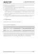
3.6. UART Interface
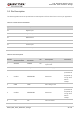
The following table shows the pin definition of the UART interface.
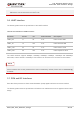
Table 8: Pin Definition of UART Interface
The UART interface supports 9600bps, 19200bps, 38400bps, 57600bps, 115200bps and 230400bps
baud rates, and the default is 115200bps. This interface can be used for AT command communication.
AT+IPR command can be used to set the baud rate of the UART, and AT+IFC command can be used to
set the hardware flow control (hardware flow control is disabled by default). Please refer to document [2]
for details.
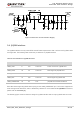
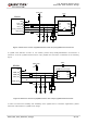
3.7. PCM and I2C Interfaces
EC21 Mini PCIe provides one Pulse Code Modulation (PCM) digital interface and one I2C interface.
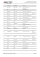
The following table shows the pin definition of PCM and 12C interfaces that can be applied in audio codec
design.
Pin Name Pin No. I/O Power Domain Description
UART_RX 11 DI 3.3V UART receive data
UART_TX 13 DO 3.3V UART transmit data
UART_CTS 23 DI 3.3V UART clear to send
UART_RTS 25 DO 3.3V UART request to send
NOTE