
Product Info

LTE Standard Module Series
EC21 Mini PCIe Hardware Design
EC21_Mini_PCIe_Hardware_Design 25 / 64
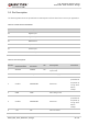
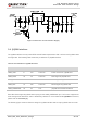
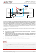
Figure 3: Reference Circuit of Power Supply
3.4. (U)SIM Interface
The (U)SIM interface circuitry meets ETSI and IMT-2000 requirements. Both 1.8V and 3.0V (U)SIM cards
are supported. The following table shows the pin definition of (U)SIM interface.
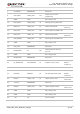
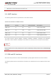
Table 6: Pin Definition of (U)SIM Interface
EC21 Mini PCIe supports (U)SIM card hot-plug via the USIM_PRESENCE pin. The function supports low
level and high level detections, and it is disabled by default. For more details of AT+QSIMDET command,
please refer to document [2].
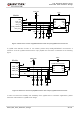
The following figure shows a reference design for (U)SIM interface with an 8-pin (U)SIM card connector.
Pin Name Pin No. I/O Power Domain Description
USIM_VDD 8 PO 1.8V/3.0V Power source for (U)SIM card
USIM_DATA 10 IO 1.8V/3.0V Data signal of (U)SIM card
USIM_CLK 12 DO 1.8V/3.0V Clock signal of (U)SIM card
USIM_RST 14 DO 1.8V/3.0V Reset signal of (U)SIM card
USIM_PRESENCE 44 DI 1.8V (U)SIM card insertion detection