
Product Info


LTE Standard Module Series
EC21 Hardware Design
EC21_Hardware_Design 69 / 120
The RI behavior can be changed by AT+QCFG="urc/ri/ring" command. Please refer to document [2] for
details.
3.20. USB_BOOT Interface
EC21 provides a USB_BOOT pin. Customers can pull up USB_BOOT to 1.8V before VDD_EXT is
powered up, and the module will enter emergency download mode when it is powered on. In this mode,
the module supports firmware upgrade over USB interface.
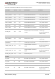
Table 24: Pin Definition of USB_BOOT Interface
Pin Name Pin No. I/O Description Comment
USB_BOOT 115 DI
Force the module to enter
emergency download mode
1.8V power domain.
Active high.
It is recommended to
reserve a test point.
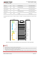
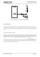
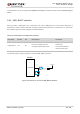
The following figure shows a reference circuit of USB_BOOT interface.
Module
USB_BOOT
VDD_EXT
4.7K
Test point
TVS
Cl ose to test po in t
Figure 31: Reference Circuit of USB_BOOT Interface