
Product Info

LTE Standard Module Series
EC21 Hardware Design
EC21_Hardware_Design 55 / 120
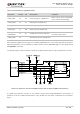
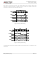
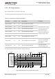
Another example with transistor translation circuit is shown as below. The circuit design of dotted line
section can refer to the design of solid line section, in terms of both module input and output circuit
designs, but please pay attention to the direction of connection.
Figure 21: Reference Circuit with Transistor Circuit
Transistor circuit solution is not suitable for applications with high baud rates exceeding 460Kbps.
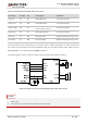
3.12. PCM and I2C Interfaces
EC21 provides one Pulse Code Modulation (PCM) digital interface for audio design, which supports the
following modes and one I2C interface:
Primary mode (short frame synchronization, works as both master and slave)
Auxiliary mode (long frame synchronization, works as master only)
In primary mode, the data is sampled on the falling edge of the PCM_CLK and transmitted on the rising
edge. The PCM_SYNC falling edge represents the MSB. In this mode, the PCM interface supports
256KHz, 512KHz, 1024KHz or 2048KHz PCM_CLK at 8KHz PCM_SYNC, and also supports 4096KHz
PCM_CLK at 16KHz PCM_SYNC.
In auxiliary mode, the data is sampled on the falling edge of the PCM_CLK and transmitted on the rising
edge. The PCM_SYNC rising edge represents the MSB. In this mode, the PCM interface operates with a
256KHz, 512KHz, 1024KHz or 2048KHz PCM_CLK and an 8KHz, 50% duty cycle PCM_SYNC.
NOTE