
Product Info

LTE Standard Module Series
EC21 Hardware Design
EC21_Hardware_Design 53 / 120
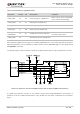
Do not route signal traces under crystals, oscillators, magnetic devices and RF signal traces. It is
important to route the USB differential traces in inner-layer with ground shielding on not only upper
and lower layers but also right and left sides.
Pay attention to the influence of junction capacitance of ESD protection components on USB data
lines. Typically, the capacitance value should be less than 2.0pF.
Keep the ESD protection components to the USB connector as close as possible.
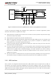
3.11. UART Interfaces
The module provides two UART interfaces: the main UART interface and the debug UART interface. The
following shows their features.
The main UART interface supports 4800bps, 9600bps, 19200bps, 38400bps, 57600bps, 115200bps,
230400bps, 460800bps and 921600bps baud rates, and the default is 115200bps. This interface is
used for data transmission and AT command communication.
The debug UART interface supports 115200bps baud rate. It is used for Linux console and log
output.
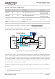
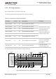
The following tables show the pin definition of the UART interfaces.
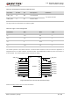
Table 11: Pin Definition of Main UART Interface
Pin Name Pin No. I/O Description Comment
RI 62 DO Ring indicator
1.8V power domain
DCD 63 DO Data carrier detection
CTS 64 DO Clear to send
RTS 65 DI Request to send
DTR 66 DI
Data terminal ready,
sleep mode control
TXD 67 DO Transmit data
RXD 68 DI Receive data