
Product Info

LTE Standard Module Series
EC21 Hardware Design
EC21_Hardware_Design 46 / 120
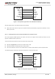
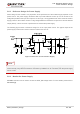
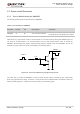
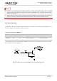
Figure 11: Turn on the Module by Using Keystroke
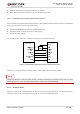
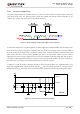
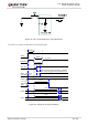
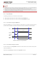
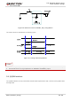
The power-on scenario is illustrated in the following figure.
V
IL
≤0.5V
V
H
=0.8V
VBAT
PWRKEY
≥500ms
RESET_N
STATUS
(OD)
Inactive
Act ive
UART
NOTE 1
Inactive
Act ive
USB
≥2.5s
≥12s
≥13s
VDD_EXT
About 100ms
BOOT_CONFIG &
USB_BOOT Pins
≥100ms. After this time, the BOOT_CONFIG
pins can b e set high level by external circuit.
Figure 12: Timing of Turning on Module