
Product Info

LTE Standard Module Series
EC21 Hardware Design
EC21_Hardware_Design 42 / 120
Hardware:
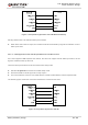
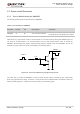
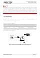
The W_DISABLE# pin is pulled up by default. Driving it to low level will let the module enter airplane
mode.
Software:
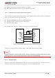
AT+CFUN command provides the choice of the functionality level through setting <fun> into 0, 1 or 4.
AT+CFUN=0: Minimum functionality mode. Both (U)SIM and RF functions are disabled.
AT+CFUN=1: Full functionality mode (by default).
AT+CFUN=4: Airplane mode. RF function is disabled.
1. The W_DISABLE# control function is disabled in firmware by default. It can be enabled by
AT+QCFG="airplanecontrol" command, and this command is under development.
2. The execution of AT+CFUN command will not affect GNSS function.
3.6. Power Supply
3.6.1. Power Supply Pins
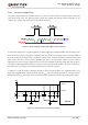
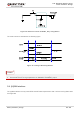
EC21 provides four VBAT pins for connection with the external power supply. There are two separate
voltage domains for VBAT.
Two VBAT_RF pins for module’s RF part.
Two VBAT_BB pins for module’s baseband part.
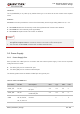
The following table shows the details of VBAT pins and ground pins.
Table 6: VBAT and GND Pins
Pin Name Pin No. Description Min. Typ. Max. Unit
VBAT_RF 57, 58
Power supply for module’s
RF part.
3.3 3.8 4.3 V
VBAT_BB 59, 60
Power supply for module’s
baseband part.
3.3 3.8 4.3 V
GND
8, 9, 19, 22, 36,
46, 48, 50~54,
56, 72, 85~112
Ground - 0 - V
NOTES