
Product Info

LTE Standard Module Series
EC21 Hardware Design
EC21_Hardware_Design 38 / 120
1.
1)
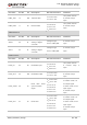
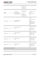
PCM interface pins are multiplexing pins used for audio design on EC25 module and BT function on
FC20 module.
1. SD card, wireless connectivity and SGMII interfaces pins are not supported on ThreadX module.
2. BT function is under development.
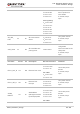
3.4. Operating Modes
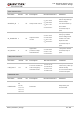
The table below briefly summarizes the various operating modes referred in the following chapters.
Table 5: Overview of Operating Modes
Mode Details
Normal
Operation
Idle
Software is active. The module has registered on the network, and it is
ready to send and receive data.
Talk/Data
Network connection is ongoing. In this mode, the power consumption is
decided by network setting and data transfer rate.
Minimum
Functionality
Mode
AT+CFUN command can set the module to a minimum functionality mode without
removing the power supply. In this case, both RF function and (U)SIM card will be invalid.
Airplane
Mode
AT+CFUN command or W_DISABLE# pin can set the module to airplane mode. In this
case, RF function will be invalid.
Sleep Mode
In this mode, the current consumption of the module will be reduced to the minimal level.
During this mode, the module can still receive paging message, SMS, voice call and
TCP/UDP data from the network normally.
Power Down
Mode
In this mode, the power management unit shuts down the power supply. Software is not
active. The serial interface is not accessible. Operating voltage (connected to VBAT_RF
and VBAT_BB) remains applied.
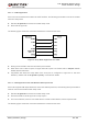
3.5. Power Saving
3.5.1. Sleep Mode
EC21 is able to reduce its current consumption to a minimum value during the sleep mode. The following
section describes power saving procedures of EC21 module.
NOTES