
Product Info


LTE Standard Module Series
EC25 Hardware Design
EC25_Hardware_Design 64 / 112
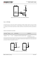
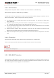
Figure 29: Reference Circuit of SGMII Interface with PHY AR8033 Application
In order to enhance the reliability and availability in customers’ applications, please follow the criteria
below in the Ethernet PHY circuit design:
Keep SGMII data and control signals away from other sensitive circuits/signals such as RF circuits,
analog signals, etc., as well as noisy signals such as clock signals, DCDC signals, etc.
Keep the maximum trace length less than 10-inch and keep skew on the differential pairs less than
20mil.
The differential impedance of SGMII data trace is 100Ω±10%, and the reference ground of the area
should be complete.
Make sure the trace spacing between SGMII RX and TX is at least 3 times of the trace width, and the
same to the adjacent signal traces.
3.19. Wireless Connectivity Interfaces
EC25 supports a low-power SDIO 3.0 interface for WLAN and a UART/PCM interface for BT.
The following table shows the pin definition of wireless connectivity interfaces.