
Product Info


LTE Standard Module Series
EC25 Hardware Design
EC25_Hardware_Design 53 / 112
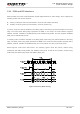
Table 12: Pin Definition of Debug UART Interface
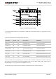
The logic levels are described in the following table.
Table 13: Logic Levels of Digital I/O
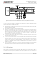
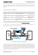
The module provides 1.8V UART interface. A level translator should be used if customers’ application is
equipped with a 3.3V UART interface. A level translator TXS0108EPWR provided by Texas Instruments
is recommended. The following figure shows a reference design.
DTR 66 DI
Data terminal ready,
sleep mode control
TXD 67 DO Transmit data
RXD 68 DI Receive data
Pin Name Pin No. I/O Description Comment
DBG_TXD 12 DO Transmit data
1.8V power domain
DBG_RXD 11 DI Receive data
Parameter Min. Max. Unit
V
IL
-0.3 0.6 V
V
IH
1.2 2.0 V
V
OL
0 0.45 V
V
OH
1.35 1.8 V