
Product Info


LPWA Module Series
BC66-NA Hardware Design
BC66-NA_Hardware_Design 36 / 59
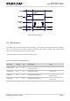
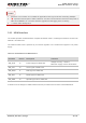
1. Transistor circuit solution is not suitable for applications with high baud rates exceeding 460Kbps.
2. “ ” represents the test point of UART interfaces. It is also recommended to reserve the test points of
VBAT and PWRKEY, for convenient firmware upgrade and debugging when necessary.
3. “*” means under development.
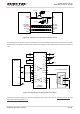
3.10. USIM Interface
The module provides a USIM interface compliant to ISO/IEC 7816-3, enabling the module to access to an
external 1.8V USIM card.
The external USIM card is powered by an internal regulator in the module and supports 1.8V power
supply.
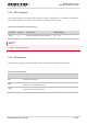
Table 11: Pin Definition of USIM Interface
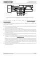
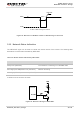
A reference circuit design for USIM interface with a 6-pin USIM card connector is illustrated below.
Pin Name Pin No. Description Comment
SIM_VDD 14 Power supply for USIM card
Voltage accuracy: 1.8V±5%.
Maximum supply current: about 60mA.
SIM_CLK 13 Clock signal of USIM card
SIM_DATA 11 Data signal of USIM card
SIM_RST 12 Reset signal of USIM card
SIM_GND 10 Specified ground for USIM card
NOTES