
Product Info


LPWA Module Series
BC66-NA Hardware Design
BC66-NA_Hardware_Design 32 / 59
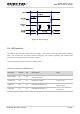
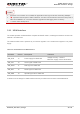
Table 10: Pin Definition of UART Interfaces
When the module enters idle mode with a fixed baud rate, please send AT via UART to wake up the
module first before sending other AT commands.
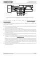
3.9.1. Main UART Port
The main UART port supports AT command communication, data transmission and firmware upgrade.
By default, the module is in auto-baud mode and it supports automatic baud rates not exceeding
115200bps. When powering on the module, the MCU has to send AT command consecutively to
synchronize baud rate with the module. When OK is returned, it indicates the baud rate has been
synchronized successfully. When the module is woken up from PSM or idle mode, the baud rate
synchronized during start-up will be used directly.
When the port is used for firmware upgrade, the baud rate is 921600bps by default.
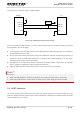
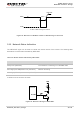
The figure below shows the connection between DCE and DTE.
Interface Pin Name Pin No. Description Comment
Main UART Port
TXD 17 Send data to RXD of DTE
1.8V power
domain
RXD 18 Receive data from TXD of DTE
Debug UART Port
RXD_DBG 38 Receive data from TXD of DTE
TXD_DBG 39 Send data to RXD of DTE
Auxiliary UART Port
RXD_AUX 28 Receive data from TXD of DTE
TXD_AUX 29 Send data to RXD of DTE
Ring Indication Signal RI 20
Ring indication signal (when there is a
SMS or URC output, the module will
inform DTE with the RI pin)
NOTE