
Product Info

LPWA Module Series
BC66-NA Hardware Design
BC66-NA_Hardware_Design 26 / 59
3.6.2. Reference Design for Power Supply
Power design for a module is critical to its performance. It is recommended to use a low quiescent current
LDO with output current capacity of 0.5A as the power supply for BC66-NA. A Li-MnO2/2S alkaline battery
can also be used as the power supply. The supply voltage of the module ranges from 2.1V to 3.63V.
When the module is working, please make sure its input voltage will never drop below 2.1V; otherwise the
module will be abnormal.
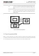
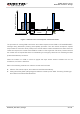
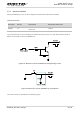
For better power performance, it is recommended to place a 100uF tantalum capacitor with low ESR
(ESR=0.7Ω) and three ceramic capacitors (100nF, 100pF and 22pF) near the VBAT pins. Also, it is
recommended to add a TVS diode on the VBAT trace (near VBAT pins) to improve surge voltage
withstand capability. In principle, the longer the VBAT trace is, the wider it should be. A reference circuit
for power supply is illustrated in the following figure.
Figure 6: Reference Circuit for Power Supply
3.7. Power up/Power down Scenarios
3.7.1. Turn on
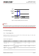
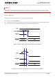
BC66-NA will be powered up after driving the PWRKEY pin to a low level voltage for at least 500ms.
Table 7: PWRKEY Pin
Pin Name Pin No. Description PWRKEY Pull-down Time
PWRKEY 7
Pull down PWRKEY to power
up the module
≥500ms