
Product Info

LPWA Module Series
BC66-NA Hardware Design
BC66-NA_Hardware_Design 22 / 59
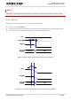
USB_MODE 47 DI
Pull down the pin
to achieve USB
download
function
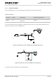
VUSB_3V3 49 PI
USB power
supply
Vnorm=3.3V
USB_DP 50 IO
USB differential
data (+)
Conform to USB 1.1
specifications.
Request 90 Ω
differential
impedance.
USB_DM 51 IO
USB differential
data (-)
Reserved Pins
Pin Name Pin No. I/O Description DC Characteristics Comment
RESERVED
2~6, 8,
21~23,
25, 26,
30~33,
44~46,
48,
52~58
Keep these pins
unconnected.
1. Keep all unused pins unconnected.
2. “*” means under development. B26 was disabled in software configuration for FCC version.
3.4. Operating Modes
The following table briefly describes the three operating modes of the module.
Table 5: Overview of Operating Modes
Mode Description of Operating Modes
Normal
Operation
Connected
In connected mode, the module is in “Active” status. All functions of the
module are available and all processors are active; radio transmission
and reception can be performed. Transitions to idle mode or PSM can
be initiated in connected mode.
NOTES