
Product Info

LTE Module Series
EG21-G Hardware Design
EG21-G_Hardware_Design 31 / 100
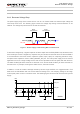
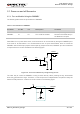
Hardware:
The W_DISABLE# pin is pulled up by default; driving it to low level will let the module enter into airplane
mode.
Software:
AT+CFUN command provides the choice of the functionality level through setting <fun> into 0, 1 or 4.
AT+CFUN=0: Minimum functionality mode. Both (U)SIM and RF functions are disabled.
AT+CFUN=1: Full functionality mode (by default).
AT+CFUN=4: Airplane mode. RF function is disabled.
1. The W_DISABLE# control function is disabled in firmware by default. It can be enabled by
AT+QCFG="airplanecontrol" command, and this command is under development.
2. The execution of AT+CFUN command will not affect GNSS function.
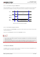
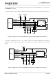
3.6. Power Supply
3.6.1. Power Supply Pins
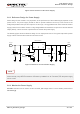
EG21-G provides four VBAT pins to connect with the external power supply, and there are two separate
voltage domains for VBAT.
Two VBAT_RF pins for module’s RF part
Two VBAT_BB pins for module’s baseband part
The following table shows the details of VBAT pins and ground pins.
Table 6: VBAT and GND Pins
Pin Name
Pin No.
Description
Min.
Typ.
Max.
Unit
VBAT_RF
57, 58
Power supply for module’s
RF part
3.3
3.8
4.3
V
VBAT_BB
59, 60
Power supply for module’s
baseband part
3.3
3.8
4.3
V
GND
8, 9, 19, 22, 36,
46, 48, 50~54,
Ground
-
0
-
V
NOTES